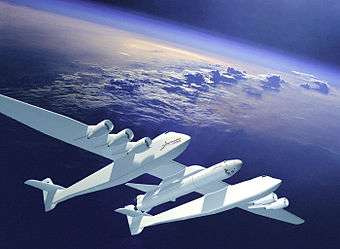
All I can discern from the links I have read and photos I’ve seen is that both fuselages have windscreens at the nose…as if flight crews are meant to see forward through them.
I haven’t found anything concerning control of the aircraft.
All I can discern from the links I have read and photos I’ve seen is that both fuselages have windscreens at the nose…as if flight crews are meant to see forward through them.
I haven’t found anything concerning control of the aircraft.
Why would they remove the windscreens in any case? There will be a lot of people on this aircraft associated solely with the launch of the rocket. They will want to (need to?) be able to see out too.
I dont know how they would cross check if the pilot and copilot are not colocated.
What a letdown! I have determined that only one cockpit is occupied.
Thanks.
I wonder why they chose to break from tradition and use the right fuselage instead of the left.
I’ll bet they have a camera in the center of the mid-wing.
Maybe they chose the right hand cockpit to give the pilot a less obstructed view of the runway.
…and you were correct in saying the payload will be center mounted. I’ll bet that mid-wing is a stout beam!
The attacment points of the outer wings are essentially fulcrums bearing not only all of the weight but all of the shearing forces placed on those wings.
Think of a bridge with two pylons in the middle with a secton of roadway stuck off to each side with no other support than those same two pylons.
The load of the center section is divided by the two pylons with all of the load of the outer sections being borne on just one.
Same with a dual hull aircraft. The center section is not going to be carrying anywhere near the load of the outer wing sections.
I’m just surprised it took us so long to get back to a launch technology developed back in the fifties/sixties.
It’s a hell of a lot cheaper to get into space from an air launch than it is from the ground.
Trying to reduce the forces involved in the flight of this airplane with its payload to an errant analogy involving a static bridge with ‘fulcrums’ borders on comedy.
The 220 ton payload hangs in the center of the middle wing section. The upward forces that provide the lift necessary to keep the plane in the air come from the full length of the airplanes wings, from tip to tip…minus the two fuselage widths and the width of the payload mounting pod. The midsection of the total wing length provides lift just as do the left and right sections…otherwise there would be no need for it.
From the above article:
The center section of the high-mounted, high aspect ratio wing is fitted with a Mating and Integration System (MIS), developed by Dynetics and capable of handling a 490,000 lb (220 t) load.[25]
Click on “aspect ratio” and read that the lift-to-drag ratio increases with aspect ratio.
The picture below comes from a glider handbook. The upper portion is directly from the handbook. The lower portion is my poor attempt to transform it into the subject airplane with its payload hanging in the center. I left of the engines, but you get the picture.
The total lifting force at the payload mounting pod (the MIS) must be 220 tons…with half of it coming from the left and half from the right. The middle wing section has got to be stout.
There’s nothing errant at all in the analogy, The principles of leverage apply to aircraft just like any other engineered structure.
Not only is half the weight of the total aircraft carried at the contact points of each outer wing those contact points bear all of the shearing forces as well that are borne by the wings.
A wing is a big lever and the attachments to the fuselage are the fulcrums.
This is why when wings suffer structural failure that’s usually where they fail.
Dream on…
The outer wings are not attached to the plane. The wing is structurally continuous from tip to tip. The fuselages are attached to and suspended beneath that structure. And the live load … the rocket … will be attached to it (in the middle) and suspended beneath it as well. Furthermore, all portions of the airfoil carry those point loads, not just the outer ends.
You are in my wheelhouse on this one WR.
That remains to be seen. What is indisputable, is that the size of the stage 1 booster, can be considerably smaller with a high altitude launch.
What you are missing is that the cross section of the wing is not uniform like a suspension bridge is. The narrower outer sections do not carry as much load per foot of wing as the broad center section.
Exactly! The wing spars run continuously from tip to tip. The engines, the fuselages and the payload are all suspended from the wing.
The fact that the fuselage surfaces surround the wing spars does not mean that the outer wings are merely attached to the outer portion of the fuselage. The structural portion of the wing runs straight through the fuselage…as in the example diagram below.
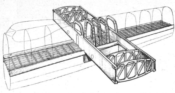
That should also be obvious from this photo of the aircraft itself.

Of course they are attached to the hull, if they weren’t you wouldn’t have a plane.
And where you hang the body of the plane from the wings crates load stress on those points.
And as an engineer, I know that the wing is designed to deal with those stresses. That’s the easy part. The stresses I am concerned about are the dynamic forces created by the fuselages moving independently to each other.
Why are you bumping this tread and recycling this conversation? It has already been thoroughly discussed.
I didn’t, it popped up down below showing two new responses.
What it’s designed for and how it plays out in reality are often two different things.
I don’t see the effects you are talking about being as likely to create failures as the total weight of the aircraft being carried by the wings and the potential stresses induced over such a long span due to any yaw that’s induced and any differentials in thrust produced by all of the engines across such a great span.
Public support is greater for a launch that people can watch. I’m not saying that’s the only reason but it’s true.
